IPSec and TLS
Goals of IPSec
If Alice receives a packet with Bob's source IP address, she cannot be sure that the packet is really from Bob. Since IPv4 does not enforce source IP address authentication, IP spoofing - forging a packet's source IP address - is a commonly used technique in cyber attacks.
For example, bots in a botnet can use source IP spoofing and DNS to mount a denial of service attack at a victim website. The bots query many different DNS servers requesting the full TXT record of a domain, which often contains many bytes of information. By spoofing the source IP address of their traffic to point to a victim website, the bots can direct the aggregate DNS response, which can be massive, to the victim website, overwhelming its servers.
IPSec provides security services at the IP layer, including
authentication of source IP addresses
confidentiality and integrity protection of packet data
authenticity of packet data; in particular, preventing packet replay
Of course, a network application or protocol can implement its own specific security mechanisms to achieve these goals, but since all network applications must run on top of IP, IPSec ensures secure networking for the many applications that are ignorant about security.
Spoofing Quiz

Spoofing Quiz Solution

If you spoof your IP address, responses to your packets will not reach you. Therefore, IP spoofing is only useful for unidirectional communication.
IPSec Modes
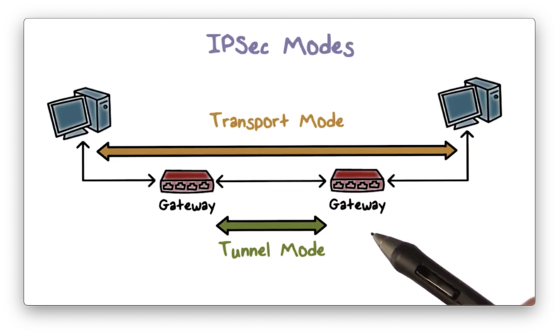
IPSec supports two operational modes: transport mode and tunnel mode. In transport mode, security protection is provided to traffic end to end, from one host to another. In tunnel mode, the protection typically is provided to traffic from the gateway of one network to the gateway of another network. Virtual private networks (VPNs) utilize tunnel mode.

Tunnel Mode
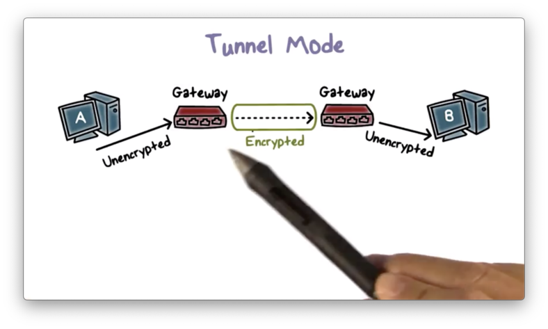
Tunnel mode is the more commonly used operation mode. Suppose we have two end hosts A and B belonging to the same company, but in two different local area networks (LANs) separated by the Internet. If there is an IPSec tunnel between the gateways of the two LANs, then traffic from A to B is automatically protected.

A emits unencrypted packets, and the gateway encrypts them before they leave the LAN. On the receiving side, the gateway to B's LAN decrypts the packets and forwards them to B.
The gateway of A's network encapsulates traffic from A to B by adding a new IP header that specifies its IP as the source IP and the IP of Bs gateway as the destination IP to make sure the protected packet is delivered to B's gateway first.

The gateway also includes an IPSec header, which contains information about the protection mechanism used.
The original packet now becomes the data/payload of the new IP packet.
IPSec Quiz

IPSec Quiz Solution

IPSec Architecture
IPSec offers several protocols to perform various functions. These include a key exchange protocol - like the Internet Key Exchange (IKE) - used for negotiating protection parameters such as cryptographic algorithms and keys, as well as two types of protection protocols: Encapsulating Security Payloads (ESP) and Authentication Headers (AH).

Encapsulated Security Payload (ESP)
ESP provides confidentiality protection through IP packet payload encryption. Additionally, ESP provides message authentication to the encrypted payload and IPSec header.
ESP Modes Quiz

ESP Modes Quiz Solution

ESP in Transport Mode
Here is the new packet layout when IPSec operates in transport mode and uses ESP.

An ESP header is inserted after the original IP header and includes the security parameter index and sequence number, which we will discuss shortly. The ESP header also includes the initialization vector (IV) used for encryption.
The ESP trailer contains padding information and a next header field, which contains information about the type of data contained in the payload, such as TCP or UDP data.
The packet payload and the ESP trailer are both encrypted, but the ESP header is not because it provides information about how to decrypt the payload, specifically in the security parameter index header. For example, this header can contain information about which algorithm and shared key to use for decryption.
The ESP header and encrypted payload are hashed together with a secret key, and the hash value is appended to the packet. This hash value serves as a message authentication code (MAC) that the receiver can use to verify the authenticity and integrity of the message.
ESP Tunnel Mode
Here is the packet layout when IPSec operates in tunnel mode with ESP.

An ESP header is added after the new IP header, and the packet payload - which contains the entire original packet plus the ESP trailer - is now encrypted. Similarly, the MAC is computed over the entire original packet, plus the ESP header and trailer. Therefore, even the original IP header fields, including the original source and destination IP address, are encrypted and authenticated.
Authentication Header
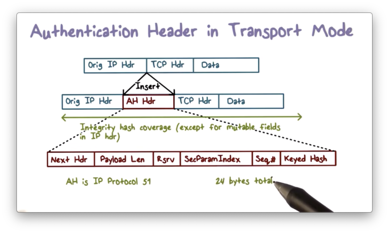
ESP does not authenticate the headers of the transmitted IP packet. If we want to authenticate the entire packet, we can use an authentication header (AH), which contains a MAC for the complete packet.
There are several fields in the IP header - such as the time to live (TTL) field - which may change in transmission. The values of these fields cannot be authenticated, and are often zeroed out when computing the MAC.
While AH does not provide encryption, we can use ESP first to encrypt the payload and then apply AH to authenticate the entire packet.
If AH is used in transport mode, the AH header is inserted after the original IP header.

If AH is used in tunnel mode, the AH header is inserted after the new IP header.

ESP and AH Quiz

ESP and AH Quiz Solution

Internet Key Exchange
If two parties wish to communicate securely, they typically need to use a security protocol that performs mutual authentication and key exchange.
For two end hosts or gateways to use IPSec for secure communications over the Internet, that protocol is the Internet Key Exchange Protocol (IKE).
IKE allows the two parties to decide the security policies for the traffic between them. Additionally, it allows the parties to agree on a set of security parameters, such as which cryptographic algorithms to use for encryption and hashing. Finally, it allows two parties to establish a shared key for confidential communication.
Security Association
The security parameters for a particular type of traffic - for example, all TCP connections from host A to host B - are described in a security association (SA).
Security associations are asymmetric. For the TCP example above, we need one SA to describe traffic flow from A to B and another to describe traffic flow from B to A.
An end host may need many SAs and uses an SA database (SADB) to store them. Each SA has a unique index in the SADB known as the security parameter index (SPI).
When A and B agree on the security parameters for their communications, each side creates an identical SA entry in their local SADB. Then, B communicates the SPI for its copy to A, which saves it as the SPI for its copy.
Whenever A and B communicate, they include the SPI on any outgoing packet so the receiver can find the corresponding SA and process it according to the agreed-upon security parameters.
The security parameters define the security mechanisms and are determined by the security policies, which are stored in a security policies database (SPDB).
SPD and SADB Fit Together
An SPD entry describes a security policy that decides the security parameters, which are stored in an SA in the SADB. The unique index for the SA of the receiver is the SPI that the sender includes in the IPSec packet header.

SPD and SADB Example
Recall that transport mode provides end to end traffic protection, while tunnel mode provides traffic protection only between the gateway of the outbound network and the gateway of the inbound network.
Transport Mode
Suppose a policy dictates that all traffic from A to B must be authenticated using HMAC with MD5 as the embedded hash function.
A's SPD stores this policy, and both A and B store an SA in their SADB containing the negotiated paramters for the policy. For example, A's SA stores the secret key for HMAC and the SPI to index the SA in B's SADB.

When A sends traffic to B, it includes the SPI in the IPSec header so that B can use it to look up its SA and then process the traffic appropriately.
Tunnel Mode
Suppose a policy states that any traffic from A's subnet to B's subnet must be sent to B's gateway D, and must be processed using ESP with 3DES.
Since C is the gateway of the A's subnet, C's SPD stores this policy, and its SADB stores the SA that has the 3DES key and the SPI for looking up the SA in D's SADB.

Outbound Processing
Before A sends a packet, it first examines the security policies in the SPD to see if the traffic needs IPSec protection. If an applicable SPD entry exists, then A retrieves the corresponding SA from the SADB and processes the packet accordingly.

Inbound Processing
When B receives the packet, it uses the SPI in the IPSec header to look up the SA in the SADB and processes the packet accordingly. Next, B looks up the SPD to ensure that A secured the packet correctly according to the policy. If so, B delivers the packet to the upper layer application.

Anti Replay
The IPSec header contains a sequence number field, which is designed to prevent replay attacks. This field is only used if AH is requested, or if the authentication option in ESP is selected.
To utilize sequence numbers, a host H must maintain a sliding window of size n - which should be at least 32. Although packets may arrive out of order, their sequence numbers should be within the window of size n.
Suppose H maintains a window where n = 50, which contains the sequence numbers from 100 to 149.
If a packet arrives with a sequence number less than 100, H rejects the packet. If a packet arrives with a sequence number greater than 149, H accepts the packet and adjusts the window to cover this packet's sequence number. For example, if H receives a packet with sequence number 199, H adjusts its window to cover 150 through 199.
Suppose H maintains a window where n = 50, which contains the sequence numbers from 100 to 149.
If a packet arrives with a sequence number between 100 and 149, H checks the number to see if it has already been seen. If yes, H rejects the packet; otherwise, H accepts the packet and records the sequence number as having been seen.
IPSec Quiz

IPSec Quiz Solution

Internet Key Exchange
Before A and B can communicate securely, they must agree upon the security parameters for their communication, such as the encryption and authentication algorithms and keys that they plan to use. In other words, they need to establish an SA before any protected communication can begin.
The Internet Key Exchange (IKE) protocol facilitates the establishment of one or more IPSec SAs between hosts. This protocol works in two phases. First, the hosts establish an IKE SA to protect the SA negotiation itself. The IKE SA is bi-directional; that is, it protects the SA negotiation traffic from both sides. Next, the hosts use this SA to protect the negotiations of multiple IPSec SAs.
IKE Phase I
The first phase of the IKE protocol serves to establish a general security association that can be used to establish multiple IPSec security associations in the second phase.
First, both sides negotiate the protection mechanism to use - AH or ESP - and also agree upon which cryptographic algorithms to use, such as AES or HMAC with SHA-1.
Then, they establish a shared secret key using a protocol such as Diffie-Hellman. Both sides can use either a pre-shared key, digital signatures, or public-key encryption to authenticate the key exchange.
IKE Phase I Example
Let's look at an example of phase one of the IKE protocol. For this example, we assume that both sides have a pre-shared secret key.

First, the initiator sends the cryptographic algorithm it proposes, along with a cookie, to the responder. The cookie is a value that the initiator can easily compute, and the responder can easily verify, such as a hash over the initiator's IP address and the current timestamp together.
The cookie proves that the initiator has done some computation and is serious about following through with the protocol. In general, cookies help to mitigate denial of service attacks where an initiator can send many requests to a responder at little to no cost.
After verifying the cookie, the responder sends back its choice of cryptographic algorithm and its own cookie to the initiator.
Second, the two parties exchange Yi and Yr - the public components of the Diffie-Hellman key exchange - combined with nonce values Ni and Nr to prevent replay attacks.
Third, both the initiator and the responder compute the same shared key according to the Diffie-Hellman key exchange as well as other keys necessary for the IKE SA.
Finally, they exchange hash values to authenticate the newly established key using their pre-shared secret key.
Diffie Hellman Quiz

Diffie Hellman Quiz Solution

Diffie-Hellman and Pre-shared Secret
In our example, the initiator and the responder have a pre-shared secret key, and, using this key as well as the information exchanged between them, they can both compute shared keys using a pseudorandom function.
Each party can build a pseudorandom function using HMAC and SHA-1 to generate a pseudorandom bitstream. SHA-1 has a property whereby the change in a single bit of input produces a new hash value with no apparent connection to the preceding hash value. This property forms the basis for pseudorandom number generation.
The pseudorandom function PRF receives two pieces of data as input - a key and a data block - both of which are passed down to HMAC.
First, the initiator and the responder compute a root shared secret, SKEYID. Each party computes this value by invoking PRF, using the pre-shared key as the key and the previously exchanged nonce values Ni and Nr as the data block.
Next, they compute a shared key to use for IPSec SA, SKEYID_d. Each party computes this value by invoking PRF, using SKEYID as the key, and the following four values as the data block: K, the shared secret key computed using Diffie-Hellman; Ci and Cr, the cookies previously exchanged between the initiator and the responder, and; the number 0.
Both parties compute the keys for IKE message authentication and encryption in a similar fashion.

Authentication of the Key Exchange
Now let's take a look at how the initiator and responder authenticate the key exchange. Both parties hash the information they have exchanged, using PRF with SKEYID as the key.
The input data block passed to PRF contains the public components of the Diffie-Hellman exchange, the cookies, the offered cryptographic algorithms, and the identities of the initiator and responder.

Each party can verify the hash value computed by the other because these values are based on information shared by both parties. By verifying these values, each party can authenticate the exchange.
IKE Phase II Keys
The second phase of IKE deals with establishing IPSec SAs. Multiple SAs can be negotiated using the protection of the same IKE SA established in the first phase of IKE. The two phases work similarly, differing primarily in how the IPSec keys are derived.
If the hosts do not require perfect forward secrecy (PFS), then they can derive all SA keys using one of the shared keys, SKEYID_d, computed in IKE phase one. The weakness of this approach is that if SKEYID_d is somehow leaked, then all of the IPSec SA keys are compromised.
Stronger security requires PFS. With PFS, both sides exchange new nonce values and perform new key exchanges before each IPSec SA negotiation. Therefore, unless the pre-shared master secret key is compromised, the keys for the current IPSec SA are secure, even if other keys previously computed have been compromised.
IPSec Summary
To summarize, if host A and host B want to communicate, the typical IPSec workflow is as follows.

Suppose this is the first time that A sends data to B that, according to policy, requires protection. The gateway of A's network and the gateway of B's network first use the IKE protocol to negotiate the IKE SA and then use that IKE SA to negotiate the IPSec SAs.
Then, the routers can use the SAs to create an IPSec tunnel between them, which protects the traffic from A to B. For example, the packet data can be encrypted and, optionally, the header information and packet data can be authenticated, depending on the SAs used.
When A terminates the connection to B, the IPSec tunnel between the two routers also terminates.
IKE Quiz

IKE Quiz Solution

SSL and TLS
One of the most widely used security services is Secure Sockets Layer (SSL) and the follow-on standard, Transport Layer Security (TLS). TLS is designed to make use of TCP to provide a reliable end-to-end secure service.
TLS can be provided as part of the underlying transport protocol suite, which allows all applications above the transport layer to benefit from the provided security services.
Alternatively, TLS can be embedded in specific application packages. For example, most web browsers come equipped with SSL, and most web servers have implemented the protocol.
TLS is not a single protocol, but rather two layers of protocols, illustrated by the following figure.

The record protocol provides basic security services to various higher-layer protocols, such as HTTP or SMTP.
Additionally, TLS defines three application-level protocols - the handshake protocol, the change cipher spec protocol, and the alert protocol - which are used in the management of TLS exchanges.
TLS Concepts
A TLS session is an association between a client and a server created by the handshake protocol. A session defines the set of cryptographic parameters to be used by each connection within the session. By defining the parameters at the session level, we avoid having to perform the expensive security negotiation process for each new connection.
A TLS connection is a transport layer relationship between a client and a server. Whereas a TLS session defines a long-term relationship, a TLS connection is transient; for example, if the client closes the connection, the connection terminates, even though the session may remain intact.
SSL Record Protocol
The SSL record protocol provides two services for SSL connections - confidentiality and message integrity - both of which are made possible by the handshake protocol. That is, the handshake protocol establishes secret keys for use in encryption and message authentication code (MAC) generation, and the record protocol uses these keys to provide those services.
This figure shows the overall transformation of application data using the SSL record protocol.

First, the host H fragments the application data into blocks that can fit in a TCP segment. Next, H compresses each block and computes a MAC over the compressed data. Third, H encrypts the compressed message and MAC using symmetric encryption. Finally, H prepends a header to the encrypted, authenticated message that includes fields specifying message length and protocol version.
H transmits the data in a TCP segment. The receiving end applies the transformation steps in reverse - decryption, verification, decompression, and reassembly - before delivering the data to the application.
The Handshake Protocol
The handshake protocol allows a client and server to negotiate security parameters, ultimately resulting in the creation of a TLS session between them.
Phase One
In phase one, the client and server share their respective security capabilities. The client initiates this phase by sending a client_hello message to the server, which contains several parameters: TLS version number, session ID, crypto suite, compression method, and initial random numbers.

After sending the client_hello message, the client waits for the server_hello message, which contains the same parameters. Therefore, at the end of phase one, both client and server know each other's security capabilities.

Phase Two
The details of phase two depend on the underlying public-key encryption scheme in use. In some cases, the server passes a certificate to the client, possibly with some additional key information, and may request a certificate from the client. Regardless, the final message must be server_hello_done, which indicates the end of this phase.

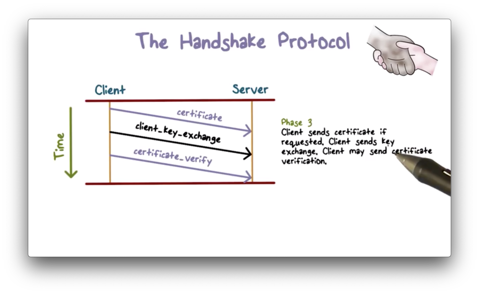
Phase Three
In phase three, the client should first verify the server's certificate. For example, the client should be able to validate that a reputable certificate authority signed the certificate.
After verification, the client can send key exchange information to the server. For example, the client can generate a secret key, encrypt it using the server's public key, and send it to the server.
Depending on the application requirements, the client may send a certificate to the server to authenticate itself. If a website is public-facing, then the authentication is typically one-way; that is, the client needs to authenticate the server, but the server need not authenticate the client. On the other hand, internal or private web servers may require mutual authentication.

Phase Four
In phase four, the client sends a change_cipher_spec message to the server and copies the pending security parameters to the current cipher spec. It then signals the completion of the handshake protocol.
In response, the server sends its own change_cipher_spec back to the client to signal that it also agrees on the exchanged security parameters. Then the server sends its own message to signal the end of the handshake.

At this point, the handshake is complete, and the client and server can begin to exchange application layer data, which will be protected using the negotiated security parameters.
TLS and SSL Quiz

TLS and SSL Quiz Solution

While transport layer protocols do rely on the IP layer, TLS does not specifically rely on IPSec.
Last updated