Protecting the TCB from Untrusted Applications
Background
The TCB must be isolated from untrusted code. This is accomplished with support from the hardware. Not only is the TCB isolated from untrusted applications. Applications are isolated from each other. When one application breaks it isn't caused by another application.
We investigate how the hardware helps us meet the requirement that the TCB is isolated/tamper proof.
Processes and Address Spaces
We trust that the hardware works.
The hardware provides two mechanisms for isolating the TCB and applications.
Processor execution modes (privilege levels). The hardware is aware of if the processor is executing untrusted code.
Privileged instructions. Some instructions cannot be executed by the processor outside of the TCB.
What exactly are we isolating? We are isolating processes. Processes are executed by a processor which executes instructions. A processor does the following
Extended Instruction Pointer (EIP) holds a pointer to the next instruction
Operands point to data which is operated on by an instruction
Executes next instruction
Addresses are logical, meaning the process uses an address that is not the actual physical address. This logical address is mapped to a physical address to access data. Two processes may reference the same logical address, but each process's logical address maps to a different physical address. Isolation is achieved by ensuring that each process can only access memory that is made available to it.
You could imagine a simple implementation where the bounds of each process's allocated physical memory is tracked by a bounds register. This bounds register can only be modified by the TCB so that untrusted code cannot give itself access to memory it shouldn't have access to.
Address Spaces on Modern Processor Architectures (Intel x86)
This is not in-depth, we focus on concepts and we focus on the Intel x86 architecture. This architecture has modes
real vs. protected modes on for 32 bit
long vs. flat modes on 64 bit.
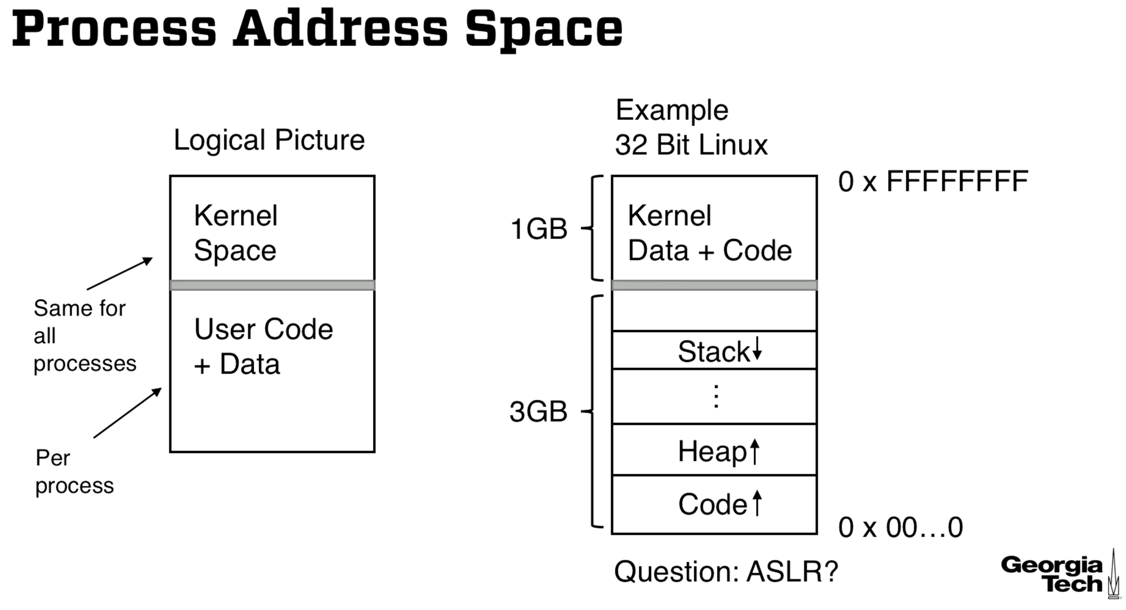
In the diagram below there are different segments of memory (stack, heap, code) for the process. These segments are further divided into pages of fixed size, not shown in the diagram. A logical address can be given by the ordered triplet (segment number, page number, page offset), where the page offset if the position within a page.
Logical/Virtual Addresses & Translation
We have a segment table that translates between logical addresses and physical addresses. Here is the formula:
SGTBR = Segment Table Base Register, this is where the segment table starts.
STE = Segment Table Entry Number
Physical address = *(SGTBR+STE*STE Size) + displacement
Intuition: We start at the segment table base register (SGTBR), the starting location of the register. STE*STE size calculates the location of the segment relative to the register. *(SGTBR+STE*STE Size) is C pointer notation for finding the location in physical memory. We add the displacement to find the physical address.
Some checks are performed to ensure we access physical memory belonging to the process, displacement <= segment size.
Segment tables are also called descriptor tables, and there are separate tables for user mode (Local Descriptor Table or LDT) and system mode execution (Global Descriptor Table or GDT).
x86 Address Translation
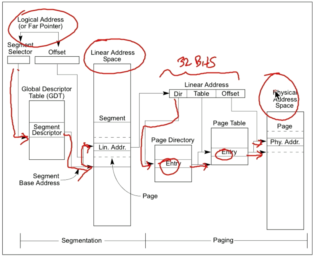
The *(SGTBR+STE*STE Size) + displacement formula seems to be a simplification. For a 32 bit architecture we take the logical address (a.k.a. far pointer) and calculate the linear address, which then allows us to calculate the physical address as shown in the diagram below.
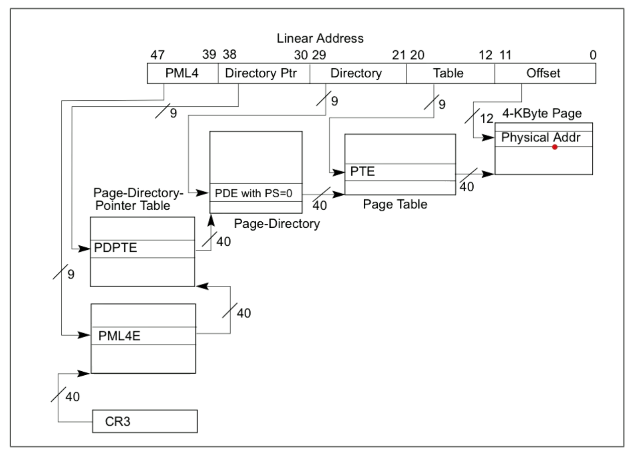
The diagram for 64 bit architectures has no GDT that maps to a linear address, we iteratively apply an offset to a memory location that brings us to the next memory location. Ultimately we end up in the physical memory as in 32 bit architectures.
PML4 stands for "Page map level 4" and CR3 is a register that points to its location.
Address Translation Observations
The tables used in address translation determine what physical memory we can access. Therefore they must belong to the OS's memory so that the user cannot modify them. If the user can modify the tables there is no isolation.
Translating logical to physical addresses could really slow down the program, but the hardware has a "translation lookaside buffer" which stores mappings from logical addresses to physical addresses.
Protecting Program Memory in the x86 Architecture
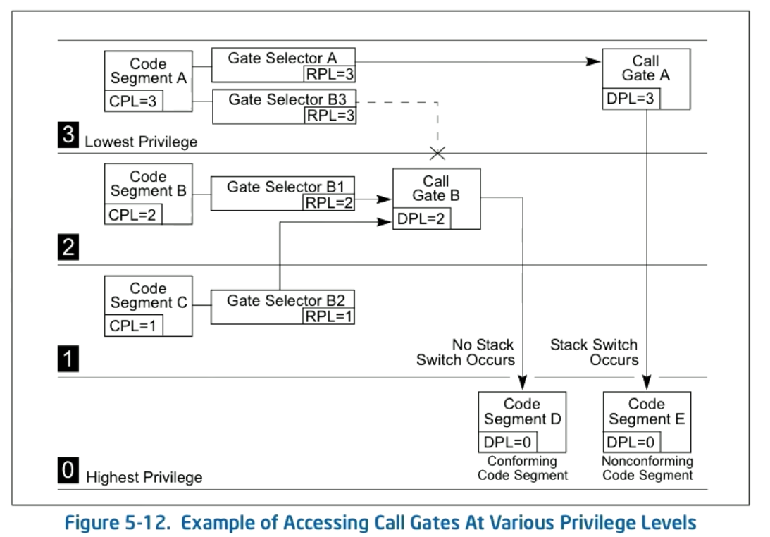
Each segment contains protection level information about the segment, called the segment descriptor protection level (DPL).
There are 4 protection levels specified by 2 bits, going from 0 to 3. 0 is the most privileged.
The current protection level (CPL) is the DPL of the code segment being executed.
Requestor privilege level (RPL) is used to stop privilege escalation attacks. The RPL is stored in the segment selector (the entries of the GDT/LDT).
Before granting access we make sure that
max(CPL,RPL)≤DPL
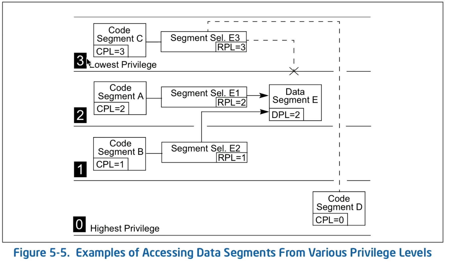
Dotted lines are for rejected access, solid lines are for successful access.
More Memory Protection Details
Conforming vs non-conforming code segments.
Code segments are either conforming or non-conforming. This determines their behavior when transferring to another code segment of a different privilege level.
For conforming code segments we can continue execution at the current privilege level, this is useful for system utilities.
For non-conforming code segments we get a protection fault unless a call gate or task gate is specified. Call gates can be used to transfer to different privilege levels (or through system call instructions). All data segments are non-conforming.
Page Level Protection
Page Protection Level (PPL) is either 0 or 1. 0 is privileged level and 1 is non-privileged level.
If the CPL is 3 we can only access PPL of 1.
There are read-write protections on pages as well.
You can also disable execution of a page.
This way you can protect a particular page within a segment.
Changing Privilege Level and System Calls
If you are trying to access code from a higher privilege level (i.e. the OS) you can come to the OS from a special entry point called a call gate. The call gate will specify the code you want to access as well as the privilege level that you can come from (given as the call gate DPL).
In the case that the code segment is conforming we can continue running at the same privilege level we came from and no stack switch occurs. If it is nonconforming we have to switch the stack.
SYSENTER and SYSEXIT
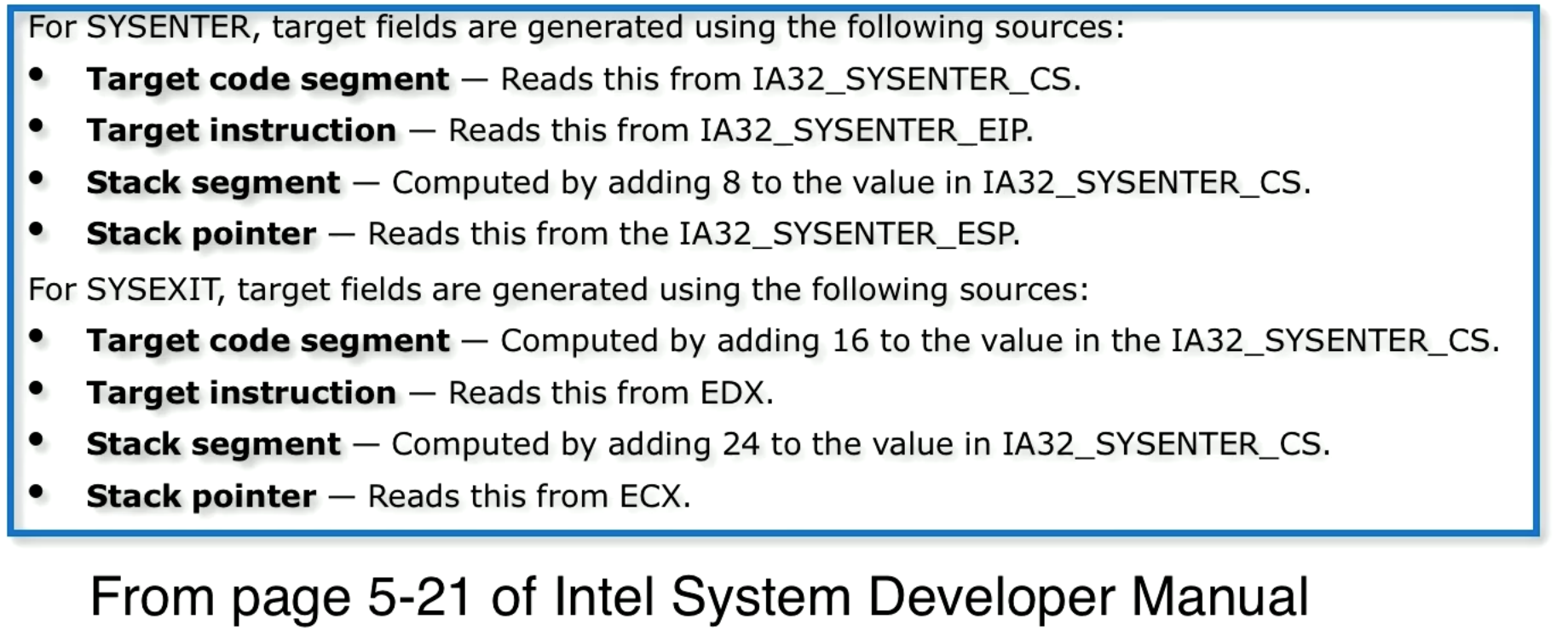
There are now instructions for system calls, SYSENTER for transferring from level 3 to level 0, and SYSEXIT for transferring from level 0 to level 3.
In the diagram below see the registers that are used to create the necessary execution context.
Privileged Instructions
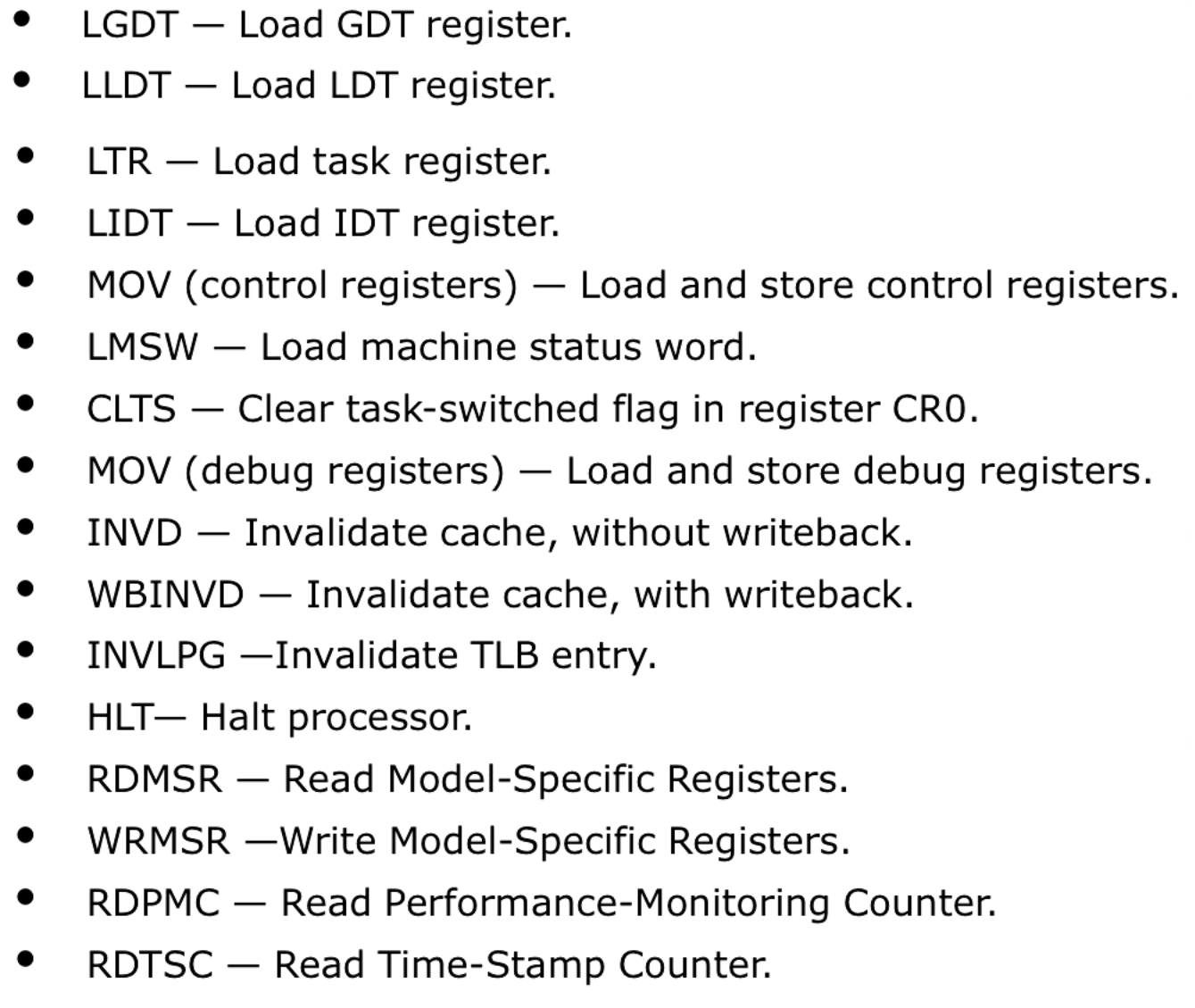
A big list of privileged instructions is given. Notably, the GDT register and LDT register control what physical memory we have access to. By making the loading of these privileged instructions we can ensure isolation.
Attacks Against Hardware and Operating Systems
Row Hammer
Although we take precautions to prevent attacks, attacks are still possible. The "row hammer" attack is where we repeatedly read memory from DRAM (some memory that we can read) we can cause bit flips in adjacent memory that gives us write access to our page table, allowing us to go where we should not.
Rootkits
Malicious software that runs in kernel mode and can change OS memory. NVD CVE-2019-6218 (entry in National Vulnerability Database) is that a malicious application can execute arbitrary code with kernel privileges (input validation issue in iOS, macOS, etc.).
Memory Protection and Software Security
System Level Software Security Techniques
ASLR is (Address Space Layout Randomization) makes it hard for an attacker to find where some specific variable is. There are some ways to get around this.
A non-executable stack. Never execute (NX) or disable execute (DX) bits. Eliminates vulnerabilities where malicious code is executed from the stack, but there are workaround attacks like return-to-libc attack.
Summary
Through understanding how physical memory is accessed via address translation, understanding memory protection, and privileged instructions, we can see how the TCB is protected from untrusted applications.
Last updated